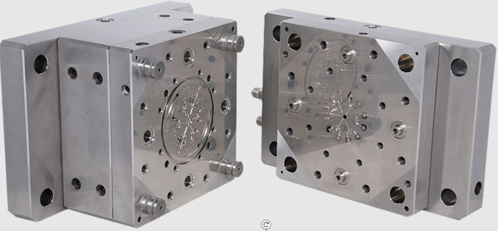
Injection molding process needs 3 major elements: raw material, injection molding machine, and mold. The process basically is that Injection molding machine melts raw material and inject it into mold, the mold opened, and we get the part. The purpose of mold is to form the melt plastic to the shape of part. It could be considered as a ”Mirror” of part, profile of part is the profile inside mold, see example in below Pic.

Here only briefs basic concept of mold including:
- Technical terms and relationship of part and mold
- The terms will be carried out by the example in next section, including Parting Line, Draft Angel/Taper, Undercut
- Major structure of mold
- Including mold concept, type, and part
Note: More structure and mechanism (including Slider, Lifter, Core pulling) will be discussed in future post.
- Technical terms and relationship of part and mold
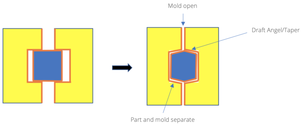
As mentioned above, after part is formed by mold, the mold needs to be opened to let the part being taken out. According to the example in below Pic., mold opened at red line which is also known Parting Line (Parting Line appears on part as well).

While the mold is opening, there is friction between the mold and part which could lead to cosmetic issue on part before they are completely separated, see illustration in below Pic. Therefore, Draft Angel/Taper shall be implemented in part and mold design.

Draft Angel/Taper is a design that could let the separation of part and mold more smoothly, see illustration in below Pic. It could affect part profile and surface finish, but it could also improve mold construct, manufacturing process…etc. If there is no dimension/assembly concern, Draft Angel/Taper shall be as big as possible.
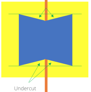
On the other hand, relative to Draft Angel/Taper, there is a design which could let the separation of part and mold not “smoothly” which known as Undercut. It shall be avoided or overcome by part and mold design.
- Major structure of mold
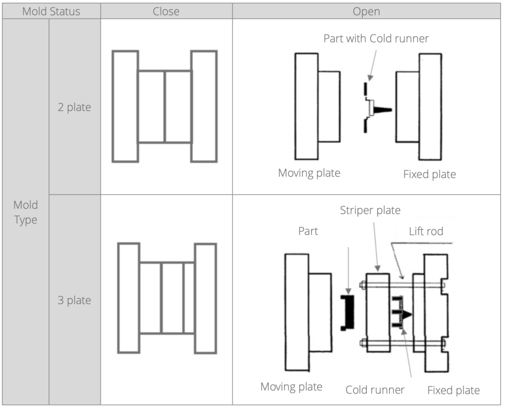
Most of the molds are at least consisted of 2 sides. During an injection molding process, the mold keeps open (letting part being taken out) and close (for the melt plastic). This movement could be achieved by moving only one side of mold, the side does not move is known as Fixed side. The other side is known as Moving/Punch side. In most of mold design, part stays at Moving/Punch side while mold open. And Moving/Punch side ejects part out of mold after mold opened.
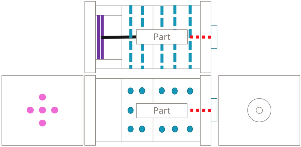
There are 2 mold type mostly being used in the industry which are 2 & 3 plate mold, the major difference in between is the Fixed side with/without Striper plate, see mold concept of both type in table-1. The purposes of Striper plate are creating space for main runner, branch runner and second Sprue, and separate cold runner from part. The application of these 2 types of molds is different, see detail difference between both mold type in table-2.

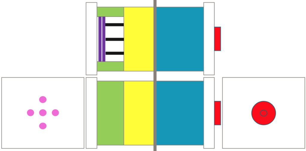
General mold concept (outside of mold), See illustration of in below Pic.
- Location Ring (red): It helps technician to load the mold to the correct position on injection molding machine.
- Back Plate (White): They let technician to fix the mold on injection molding machine.
- Fixed side/Cavity Plate (Blue): One of the mold plates at fixed side which contacts to part.
- Moving side/Core Plate (Yellow): One of the mold plates at moving side which contacts to part.
- Spacer (Green): It creates space for ejection system movement.
- Ejector (Black): It push part out of moving side and attached/driven by Ejector Plate.
- Ejector Plate (Purple): It attaches all Ejector and driven by injection molding machine.
- Knock Out Hole (Pink): These holes on moving side back plate, they let injection molding machine reaches Ejector Plate by passing through moving side back plate.
- Parting Line (Grey): Separation of fixed side and moving side.
General mold concept (inside of mold), See illustration of in below Pic.
- Runner(red): System for melted plastic travel from outside of mold into part area in mold.
- Cooling (blue): Adjust mold temperature and take out extra heat content of melt plastic.
- Ejector (Black): It push part out of moving side and attached/driven by Ejector Plate.
- Ejector Plate (Purple): It attaches all Ejector and driven by injection molding machine.
