Runner is a system (path) of mold for plastic material flow travel from outside of mold into cavity area, see concept in pic.-illustration of mold.

- In which
Red: Runner system, Orange: location ring (a part of mold to connect to injection unit), Joint of red line and part: Gate (entrance of cavity) - During production, plastic inside mold could be divided into 2 parts: runner and part.
Here discuss 3 runner systems
- Cold runner
a. Introduction to Cold runner
b. Mold type for different Cold runner - Hot runner system
a. Introduction to Hot runner system
b. Valve gate type Hot runner system - Semi Hot runner system
- Cold runner
The injection molding process with Cold runner design mold produces parts and Cold runner. The runner part plastic mostly become waste, or lower grade raw material after recycling.


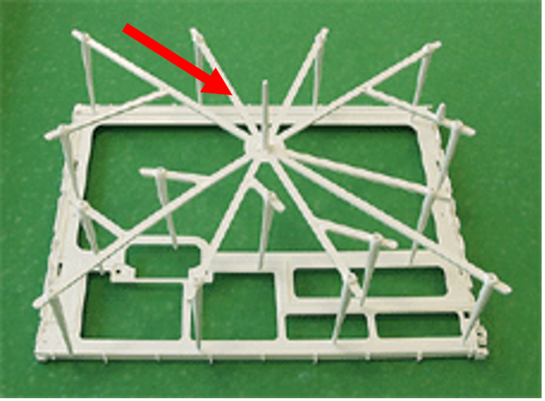
Generally, Cold runner could be divided into areas below, see detail in pic.-illustration of Cold runner type-1
- Injection entrance
Where material enters mold. (close to location ring) - Sprue
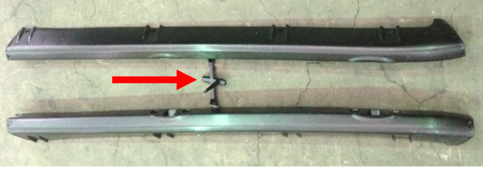
Let material flow travel to same level of Main runner. - Cold slug well
Let lower temperature material flow stay instead of into cavity. - Main runner
Let material flow travel to Branch runner. - Branch runner
Let material flow travel to Gate. - Gate
Let material flow travel into cavity.

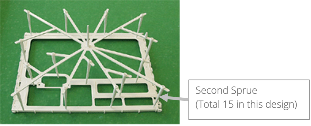
Some parts need many even distributed Gates to fulfill injection molding process requirement. The Gates are at different level with Main runner, material flow needs to travel through second Sprue then reach Gate, see concept in pic.-illustration of Cold runner type 2.

- Hot runner system: The function of Hot runner system (also known as HRS) is to keep plastic in this system stay melted by providing heat. The material flow travels inside HRS from Injection entrance to end of Hot tip, see concept in pic.-illustration of Hot runner system inside mold. It brings following effects to injection molding process:
- Reduce waste of raw material: Plastic material flow in HRS stays melted and keep joining next injection molding cycle. Each shot weight of mold with HRS will be less comparing to mold with Cold runner.
- Reduce machine load: Less shot weight stands for less plastic shall be injected by inject molding machine during production, this can reduce injection pressure requirement.

Note: Red: a. Plastic material flow, b. This is a concept for basic 2 Gates/Cavities design.
HRS is an “Additional” system to be installed inside mold (mostly at fixed side of mold), generally it consists of following items:


Valve gate type Hot runner system: The major purpose of Valve gate type Hot runner system (also known as HRS) is to give user ability to adjust the timing of when material flow leaves each Hot tip. Weld line is the joint of material flow come from different directions; it could lead to part strength / cosmetic issue. By controlling the timing of material flow enter into cavity area, it is possible to move Weld line to an area on part where is acceptable to have defects.


Valve gate is an “Additional” system to be installed into HRS, generally it consists of following items (See concept in table-4)
- Valve pin: control material flow.
- Cylinder: control the movement of Valve pin.

Material flow can NOT leave Hot tip & enter cavity area.

Material flow CAN leave Hot tip & enter cavity area.
- Semi Hot runner system: This is a combination of Cold runner and Hot runner system. When material flow leaves Hot tip, it enters a small piece of Cold runner, then into cavity. Semi Hot runner system allows most flexibility of gate location and less waste of raw material. Some parts design has higher cosmetic requirements, this system is an option as well, see concept in Pic.-Semi Hot runner system concept.
Mold with Semi Hot runner system able to move / hide Gate and fulfill part design requirement.

Note: Blue: part, Orange: area accept no defects (Gate, Eject mark…etc.), Green: Cold runner
In the end, we compare 3 runner type and list items shall be considered during mold design stage.
