Here discuss 4 plastic characteristics which being mostly considered in product/process development, and how they affects through out the entire product life cycle.
- 4 Temperature
- Shrinkage Rate
- L/t ratio
- MI
Note: Polymer manufacturer shall provide these information.
4 Temperature
Each kind of plastic behaves differently when at 4 different temperature This information help designer to decide injection molding equipment/tool/plastic raw material.
- Glass Transition Temperature (Tg)
- Heat Deflection Temperature (HDT)
- Melting Temperature (Tm)
- Pyrolysis Temperature
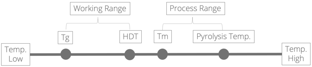
This axis represents temperature from low(left) to high (right), and the relative position of 4 temperature to subject plastic.
- Working Range: Represents the environment temperature parts could work. Designer shall select suitable plastic according to desired part working environment. Such as in a car, parts in engine bay and passenger area endure different environment/work temperature, different plastic shall be selected respectively.
- Process Range: Represents the temperature required during injection molding process. Designer shall select suitable injection molding machine and mold steel.
Shrinkage Rate
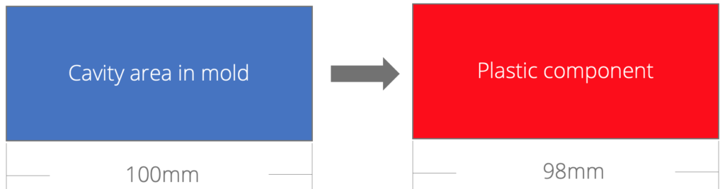
Plastic volume expends when temperature go up and shrinks when temperature go down. The size/dimension “Difference” of Plastic between Plastic at Process Range and Working Range (room temperature). This information help designer to decide profile/dimension “in mold”
Note: When implementing shrinkage rate into mold design, Designer shall also consider the test method provided by supplier. Different mold design ( Gate / Venting…etc.) could affect the shrinkage rate too. Designer shall consider possible factors and implement corresponding precaution in order to prevent welding in mold.
Shrinkage test method concept: Suppose a mold has 100mm cavity area, a plastic part made by this mold has a dimension 98mm. The shrinkage rate of subject plastic is 2%.
L/T ratio
It stands for Material flow Length / Material flow Thickness, an indicator of that how much area in mold could be filled by plastic material flow “effectively” with certain injection pressure. This information help designers to “predict” possible defect on plastic part, and apply suitable Gate, Runner system, Venting…etc. in mold design.
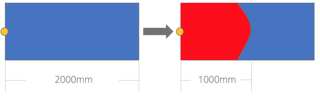
- L/T ratio test method concept: Suppose a mold has 2000mm length, 3mm thickness cavity area. Inject plastic material into the mold, and the material flow reaches 1000mm. L/T ratio of this plastic is 1000/3≒333.
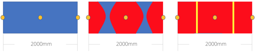
Discussion: Suppose a mold has 2000mm length, 3mm thickness cavity area. Inject plastic material into the mold (L/T ratio of this plastic is 220)
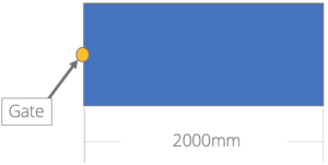
One of the solutions could be : increase gate qty. from 1 to 3. Although this solves L/T issue, it also leads to welding line issue on part. Welding line may lead to appearance issue and lower the part strength.
MI
MI stands for Melt Index, also known as MFI (Melt Flow Index), MFR (Melt Flow Rate). MI indicates fluidity of plastic.
- MI High, Fluidity High
- MI Low, Fluidity Low
This information help designer to predict required machining precision, Venting, matching process…etc. in mold design.
Note: Generally, MI value of plastic come from ASTM D1238 (Standard Test Method for Melt Flow Rates of Thermoplastics by Extrusion Plastometer)