Molding process is a complicated cross interaction between raw material, mold, injection molding machine (IMM), and some related equipment. There are hundreds of settings in these systems. How/where do we start??
Here discuss the process to find the most suitable molding parameter setting to process the molds, it is suggested to perform this process to each mold during its first trial shot. The molding parameter settings found by this process able to let the whole equipment produces stable parts and following trial shot and mass production could just follow the same setting to save the time required for setup.
Here I will separate this molding process establishment into 3 steps and what shall be doing in each step:
Part-A Find the parameters have reference to follow
Part-B Discuss the approaches to find out the parameters have no reference
Part-C Optimize the molding parameters
Part-A Find the parameters have reference
Although there are dozens of molding parameters to be settled, we do not have to start all over again for each new mold. There are some characteristics/properties are general/common to the plastic industry, and some parameter settings are designed (already known/determined during mold design phase). This section mentions the parameter settings and subject reference respectively, technician can input the same into equipment accordingly.
- Raw material property sheet from supplier
The information is normally a range, it shall be adjusted according to actual situation.
Mold temp.
Barrel temp.
Hot runner temp. - Raw material type
- Screw speed
Ex. Raw material with glass fiber requires lower screw speed. - Back pressure
Ex. Transparent raw material requires higher back pressure.
- Screw speed
- Mold design
Clamping force
Calculated by mold designer.
Ejector stroke
Calculated by mold designer.- Plasticizing
Depending on the IMM spec. as well.
This is also related to cushion, ensure cushion is not “0” by adjusting plasticizing.
- Plasticizing
- Technician’s experience
Delay time
Decompression
Safety force
Opening stroke
Ejector force
Part-B Discuss the approaches to find out the parameters have no reference
In this part, we test the mold capability and run study/procedure to find out the parameter settings which have no reference.
Fill time study
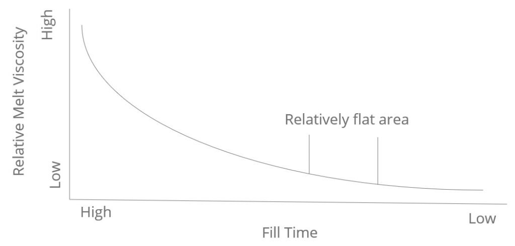
It is the time for IMM to perform injection phase. If injection speed too low, part will be easy to have short shot. Injection speed shall not be too high in order to reduce maximum pressure and protect IMM/mold. The most suitable fill time shall be somewhere at relatively flat area of the curve, see example in Pic.-1
- A. Step:
- Set the injection speed to maximum value.
- Set switchover to 50% of plasticizing setting value.
- Perform molding process.
- Find the full part by changing switchover position. (increase the part weight till the weight cannot be increased anymore)
- Record values including: Plasticizing, Decompression, Switchover position, Maximum pressure, Fill time, Part weight
- Set next injection speed. (reduce with interval 10 mm/s) and repeat from step 1 until injection speed setting 20 mm/s
- Find Relative Melt Viscosity by Maximum pressure (bar) * Fill time (sec)
- Generate graph as Pic.-1
- Select suitable fill time and switchover as parameter setting.
- B. Items to be checked:
- Injection speed, Part weight, Part appearance, Plasticizing, Decompression, Switchover position, Maximum pressure, Fill time
Cavity balance study (for hot runner multi cavity mold only)
The 95~98% weight of each cavity of a shot part shall be within a specification base on a shot weight.
- A. Step:
- Run IMM with injection speed and switchover found in fill time study.
- Find the full shot weight by ticking Switchover position.
- Find the full part weight for each cavity.
- Find the 90%-part weight by ticking Switchover position.
- Find the heaviest cavity.
- Change switchover to have the heaviest cavity part weight at 90%.
- Compare weight of part from each cavity , find the most heavy and light cavity.
- Check the weight difference between part in previous step.
- If cavity weight cannot be claimed balance, change the hot runner tip temperature to balance the weight. Increase temperature to increase the part weight of the tip/cavity / Reduce temperature to reduce the part weight of the tip/cavity,
- B. Items to be checked:
- Part weight, Part appearance
Switchover weight
It is an indicator of the amount of material being injected into cavity during injection phase.
- A. Step:
- Record weight of the part of the shot by changing the switchover position.
- B. Items to be checked:
- Part weight (95~98% part weight of full part)
Holding (Gate freeze) time study
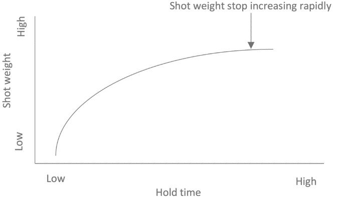
It is the time for gate to cool down and freeze, in order to keep plastic inside cavity area. The most suitable Holding time shall be somewhere the shot weight stop increasing rapidly, see example in Pic.-2
- A. Step:
- Find 60% of the maximum pressure of the setting found in “Fill time study” and use the same as holding pressure setting.
- Run molding process with 0.5 holding time and record the part weight.
- Repeat previous step with different holding time from 1.0, 1.5, 2.0, 2.5……etc. until shot weight stop increasing rapidly.
- Generate graph as Pic.-2
- Select suitable Holding time as parameter setting.
- B. Items to be checked:
- Part weight, Part appearance
Hold pressure study
There shall be at least 2 holding pressure setting for each mold. First setting is to fill the part completely, second setting is to keep plastic inside cavity area. The most suitable Holding pressure shall be part dimension actual reflects the mold dimension. and part weight stop increasing rapidly.
- A. Step:
- Find 60% of the maximum pressure of the setting found in “Fill time study” and use the same as holding pressure setting.
- Run molding process with holding time found in Holding time study.
- Record the part weight and dimension respectively.
- If the dimension is small, increase holding pressure. If the dimension is big, reduce holding pressure.
- Select suitable Holding pressure as second parameter setting.
- First Holding pressure setting would be between the maximum pressure and second hold pressure setting.
- The sum of time setting of first and second hold pressure setting shall be equal to the time period found in “Holding (Gate freeze) time study”
- B. Items to be checked:
- Part weight, Part appearance, Dimension
Clamping force study
The force for IMM to close the mold during molding process. The most suitable clamping is “during injection molding process, mold breath is less than 0.02mm”.
- A. Step:
- Install dial indicator on the mold to monitor the mold breathing during molding process.
- Find 60% of the maximum clamping force of the IMM capability and use the same as clamping force setting.
- If mold breathing is more than 0.02mm, increase the clamping force. If mold breathing is 0 mm, reduce the clamping force.
- Find the clamping force could generate mold breathing within the range between “0~0.02mm” and it is the parameter setting.
- Add 15% more to the clamping force value for safety. That is the theoretically most suitable Clamping force.
- B. Items to be checked:
- Part appearance, Clamping force, Mold breathing
Cooling time study
The time for part to cool down inside the mold cavity during molding process. Cooling time shall not be less than the HDT of the raw material.
- A. Step:
- Install Infrared thermal imager to monitor moving side parting surface temperature.
- Run the molding process with cooling time from 0, 1, 2 sec.……etc.
- Check part temperature and compare to HDT.
- If cavity temperature higher than HDT, increase the cooling time.
- If cavity temperature lower then HDT, reduce the cooling time.
- Select suitable cooling time as parameter setting.
- B. items to be checked:
- Choose the minimum one>>Plasticize time, Robot movement required time, Plastic required cooling time
Pressure loss study
To understand the maximum pressure difference at different area inside mold.
- A step:
- By reducing the amount of plastic being injected into mold, Find the part with part weight at 100%, 90%, 60%, 30%, plastic fills up to “only hut runner filled up to gate point”, “Material purged through hot runner systems or fill cold runner sprue”, “Material purged through machine nozzle”
- Record the maximum pressure of each run.
- B. Items to be checked:
- Part weight
Weight capability study
The weight variation of each shot shall be within 0.5%, as the prove of stability of found parameter setting is enough.
- A. Step:
- Run molding process for at least 30 cycles and record weight of each shot.
- Find the difference of weight of each shot.
- B. Items to be checked:
- Part weight
Process data
The data shows a stable molding process and no alarm record in between to ensure the molding process parameter setting stability.
- A. Step:
- Run 4 hours with the setting found in benchmarking study.
- Load and study the process data from IMM
- B. Items to be checked:
- Process data of IMM
Part-C Optimize the molding parameters
After the parameter setting are settled by the scientific approach mentioned above, the molding process still can not produce good parts. There may still be cosmetic/dimension issues to be solves, and it is the work to be done in this part. All of the parameter settings are adjustable, the purpose of molding process is to produce good parts continuously/consistently. Check B-6 for possible countermeasure for part issues.