As any manufacturing process, defects can happen and negatively affect your product quality and productivity. To help you avoid this problem and create consistently great products, here discusses 35 different kinds of common plastic part issues (see table-1), their background and possible countermeasure.
Before start identifying the issues, it is suggested to complete following actions in advance:
- Document it immediately/fully
- Develop a baseline process
The process which can produce parts with no/least issues. - Determine what is not the problem
| No. | Issues | Description |
| 01 | Flash | Excessive plastic appears at parting line/split line area. |
| 02 | Short shots | Part does not have comprehensive cavity profile |
| 03 | Flash and Short Shots at same part | 2 conditions above appears on a same part |
| 04 | Burn mark close to parting line | Char appears on part surface |
| 05 | Burn mark close to gate | Char appears on part surface |
| 06 | Weld line | Additional line (usually next to shut off) appears on part surface |
| 07 | Sinks and Voids | Part thickness lower than design, usually at thick section of part |
| 08 | Blisters and bubbles | Trapped air in part |
| 09 | Splay | Silver or white streaks appear on part surface |
| 10 | Jetting | Flow lines that look like snake tracks on part surface |
| 11 | Gate blush | Cloudy or hazy discoloration of the plastic appears on part |
| 12 | Poor color distribution and streaking | Unexpected different color flow randomly appears on part |
| 13 | Poor surface, non-uniform gloss | Uneven part surface |
| 14 | Ripples | Uneven part surface |
| 15 | Part sticking | Unable to remove part from mold |
| 16 | Ejector pin marks | Whiteness/Deformation appears on part surface at ejector pin area |
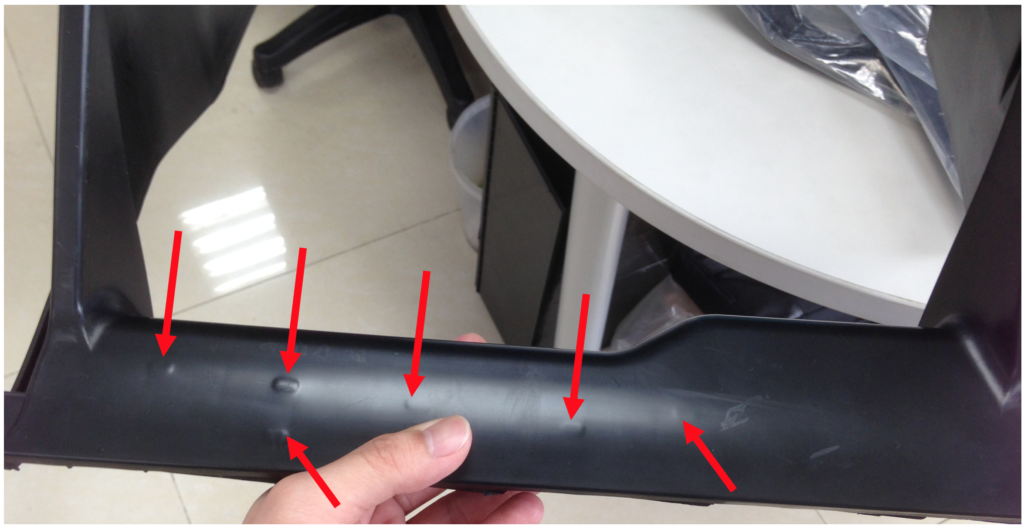
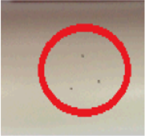
| 17 | Black spots | Unexpected different color spot randomly appears on part |
| 18 | Cracking | Part cracks or at similar area and repeatedly on many shots |
| 19 | Delamination | Peeling appearance on part surface |
| 20 | Brittleness | Part cracks or breaks at a much lower stress level than would normally be expected based on the virgin material properties |
| 21 | Warp | Inconsistent deformation of the part which making it nonconforming to the shape of the cavity. |
| 22 | Dimensional Variations | Part is too small overall |
| 23 | Dimensional Variations | Part is too large overall |
| 24 | Dimensional Variations | Part is too small close to gate |
| 25 | Dimensional Variations | Part is too large close gate |
| 26 | Dimensional Variations | Part is too small at end of filling |
| 27 | Dimensional Variations | Part is too large at end of filling |
| 28 | Dimensional Variations | Dimensional Inconsistency |
| 29 | Process Problems | Hot runner blockage |
| 30 | Process Problems | Hot runner shorts (random in cavities) |
| 31 | Process Problems | Nozzle drool |
| 32 | Process Problems | Nozzle freeze-off |
| 33 | Process Problems | Nozzle stringing |
| 34 | Process Problems | Occasional part hang-up |
| 35 | Process Problems | Sprue sticking |
01. Flash
- Background
Flash can be led by excessive pressure in the mold compared to the clamping force available or because of mold damage. It is important to analyze when it is occurring. It is best to make a fill only short shot and to see whether the flash is happening during filling or during holding. See Flash illustration in Pic.-1 and Pic.-2. - Possible countermeasure
- Flash occurs during holding
Reduce switchover position
Reduce hold pressure if possible
Check to determine if proper clamping force is available - Flash occurs during filling
Check to determine that proper clamping forces are available - Material Viscosity is too high
Check fill time/pressure consistency - Mold has been damaged and parting line does not shut off
Fix the mold - Material viscosity is too low; flashing through poor shut off areas
Check viscosity as above
Determine cause of viscosity variation
Repair mold - Flashing during fill; filling too fast for mold conditions.
Check fill time against previous fill times and reset if necessary
- Flash occurs during holding
02. Short Shot
- Background
Shorts shots mean there is no pressure at the end-of-filling. It can be led by not enough holding in the cycle. If no machine filling or pressure setting change observed, this generally means a viscosity change has occurred. The viscosity is increased to a condition where the plastic no longer flow. See Short Shot illustration in Pic.-3. - Possible countermeasure
- Plastic temperature is too low
Measure melt temperature independently form machine settings - Injection rate is too slow
Monitor fill time and correct if necessary - During filling, insufficient injection pressure was available to maintain fill speed setting
Raise first-stage pressure - During filling, pressure is abundant and fill time is too slow
Check for nozzle obstruction - Viscosity of the material is too high
Purge into the air and observe the injection pressure
Change material
Increase hold pressures to compensate for material increase in viscosity
- Plastic temperature is too low
03. Flash and Short Shots at the Same Time
- Background
Generally, it indicates a change in the pressure distribution during filling due to a dramatic viscosity change. It can also be caused by insufficient clamping force. - Possible countermeasure
- Check clamping force availability
- Check viscosity
- Check fill time
- Check melt temperature
- Check mold temperature
- Determine that the material is correct
04. Burns mark close to parting line
- Background
It generally led by trapped compressed air causing high temperature, which ignites the plastic thereby causing char. The air inside cavity needs to be released more effectively. See Burn mark illustration in Pic.-4 and Pic.-5. - Possible countermeasure
- Clean vents
- Add more vents
- Reduce injection rate
05. Burn mark close to gate
- Background
If streaks exist consistently near the gate, it generally means for most materials that there is a rough spot at the gate that should be polished out of the mold. - Possible Countermeasure
- Polish the gate area to eliminate the rough condition
- Reduce the injection rate
06. Weld line
- Background
- It is actually a glue joint of two plastic flow fronts, and it will appear on part surface if they do not well re-entangle.
- Low visibility Weld line requires the material at a low enough viscosity, the flow front must be clean, there must be sufficient pressure to cause bonding, and the pressure must be held for a sufficient time to allow the material to solidify.
- Also, there is often air entrapment. Weld line area must be well vented.
- See illustration in Pic.-6 and Pic.-7
- Possible Countermeasure
- Check viscosity and correct if necessary
- Check melt temperature
- Check fill time
- Check mold temperature
- Confirm the part is properly packed
- Raise hold pressure and confirm the gate is sealed
- Check gate seal time
- Confirm the cavity is adequately vented at Weld line area
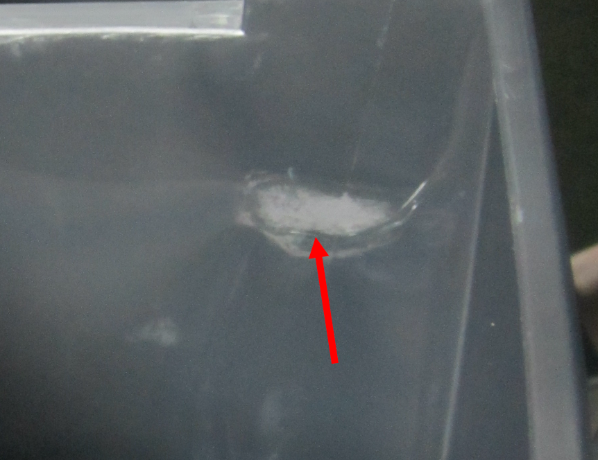
07. Sinks and Voids
- Background
- As material cools and shrinks in a mold, insufficient holding will lead either sinks on the outer portion of the part or voids in the center.
- Sinks and voids happen more in thick sections where high are the last to cool, or in areas extremely far from or very close to the gate.
- Classic sinks in thick areas and far from the gate indicate insufficient holding and possibly increased viscosity of material.
- Sinks close to the gate generally indicate lack of gate seal and possibly decreased viscosity, which is usually led by increased plastic temperature.
- Voids vacuum bubbles due to a lack of material during cooling.
- See Sink illustration in Pic.-8
- Possible Countermeasure
- Increase viscosity
Check melt temperature and adjust it if necessary - Holding pressures are too low (end of fill sinks and thick sections only)
Raise hold pressure - Injection time is too short to allow gate seal
Increase injection forward/hold time - Mold temperature is too high to affect gate seal
Lower mold temperature
- Increase viscosity
08. Blisters and Bubbles
- Background
Blisters and bubbles are trapped air or gas inside part, it is important to determine the makeup of the foreign material including Moisture, Trapped air, Degraded polymer molecules, Degraded additives. Usually, blisters and bubbles exist with splay. - Possible Countermeasure
- Dry the material
- Reduce melt temperature
- Reduce residence time
- Increase back pressure to remove trapped air
- Change material additives
- Change to virgin material if regrind virgin mix is being used
- Increase holding pressure-use this action as a last resort because it generally covers up the problem
- Remove sprue break or reduce decompression
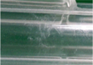
09. Splay
- Background
Splay can be led by several liquids or gases, which can be moisture from un-dried material, trapped air, degraded polymer molecules, or degraded additives. See Splay illustration in Pic.-9. - Possible Countermeasure
- Dry material
- Increase back pressure to remove trapped air
- Change the screw type to remove trapped air
- Check material temperature and residence time to eliminate molecular degradation and additive degradation
- Keep moisture from condensing on the mold surface
- Remove sprue break
- Reduce or eliminate decompression
- Check L/D of screw; if lower than 16:1, try higher L/D or different screw design
10. Jetting
- Background
- When entering the cavity through the gate, plastic does not get impinged on any portion of the cavity and is allowed to fly unobstructed into the cavity for a long distance before attaching to the wall.
- Sometimes jetting can be corrected in a mold by reducing injection speed or decreasing the viscosity of the polymer. However, this is generally not a robust solution.
- Jetting should be fixed by changing the gate configuration to allow the plastic to impinge on a wall or insert into the cavity.
- Possible Countermeasure
- Modify the gate to allow impingement of the plastic on the wall of the cavity.
- Short term: slow down the injection ram, increase the melt temperature or adjust the mold temperature to make the plastic stick to the cavity (generally not good long-term fixes).
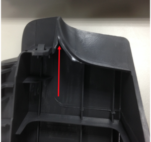
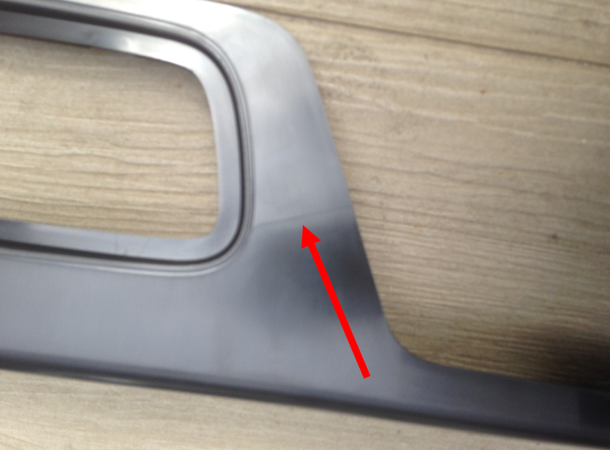
11. Gate Blush
- Background
- Gate blush is led by an erosion of the first plastic enters gate during filling. Erosion is a chemical reaction led by high temperature, the best ways to eliminate gate blush is to minimize the temperature at the area by reduce the speed of flow and/or increase the cooling in the area.
- The other possibility is to change the way the plastic impinges on the part, by angling or moving the gate.
- See Gate blush illustration in Pic.-10 and Pic.-11.
- Possible Countermeasure
- Lower injection speed
- Lower mold temperature in the gate blush area
- Change the angle of impingement between the plastic and the cavity
- Change the gate location
12. Poor Color Distribution and Streaking
- Background
This could be led by- Poor mixing and/or melting in the barrel of the injection molding machine.
It can be led by not enough effective length of the barrel for the specific plastic. The effective length of the barrel can be significantly changed or increased by having the different barrel temperature profile, and increasing the rear zone temperature can make the plastic stick to the barrel early and cause better mixing. - Contamination.
- See illustration in Pic.-12
- Poor mixing and/or melting in the barrel of the injection molding machine.
- Possible Countermeasure
- Check melt temperature to ensure that it is in the mid-range.
- Purge and look at the condition of the melt. If cold pellets exist, change temperature profiles and increase back pressure to improve melt homogeneity.
- Change material to virgin if contamination is suspected.
- Change screw type.
- Change machine to one with a larger L/D.
- Change to virgin material.
- Slow screw speed.

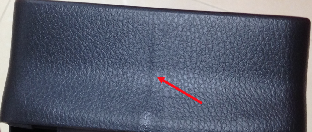
13. Poor Surface Finish or Non-uniform Gloss
- Background
This could be led by- Plastic not being well packed.
- A film layer between the plastic and the cavity.
This film layer could be a gas, or trapped air and usually observed at the area close to parting line and away from the gate. Does the gloss gradient correlate with the cavity pressure gradient? - Viscosity of the plastic may be too high.
- The gloss on the part could be caused by cooling rate change.
- Poor surface finish could be moisture on the surface of the mold, especially in high humidity conditions.
- Possible Countermeasure
- Increase holding pressure, increase or clean vents, and decrease cavity pressure gradient
- Change material
- Check viscosity
- Check melt temperature
- Check fill time, material, and mold temperature
- Check melt temperature and mold temperature against set-up sheet
- Clean mold surface: keep condensation from forming on mold
14. Ripples
- Background
- It is caused by scooching of the melt at the interface between the solidified plastic and the mold surface. The general cause of this is too slow a holding rate caused by an increase in viscosity.
- Radiating outward from the gate towards the end of the cavity generally caused by TOO SLOW holding or INCORRECT mold temperature.
- Possible Countermeasure
- Check viscosity
- Check melt temperature
- Measure fill time
- Check mold temperature and adjust if necessary
- Increase holding rate
15. Part sticking
- Background
- It is generally caused by over or under pressurizing various parts of the mold.
- On parts with deep cavities such as a glass or trash can, overpacking will cause the part to stick in the cavity, while under packing will cause the part to shrink onto the core. If a part has a long flow length and the part is sticking at one area of the mold, recognize that there is a pressure change in that area of the mold, either increased or decreased. Determine which is appropriate and then make the corrective action.
- Possible Countermeasure
- Adjust the holding and holding pressure
- Adjust injection forward time to affect gate seal or discharge
- Check viscosity to determine the cause. If viscosity has changed, check cause (melt temperature, fill mold temperature, or material)
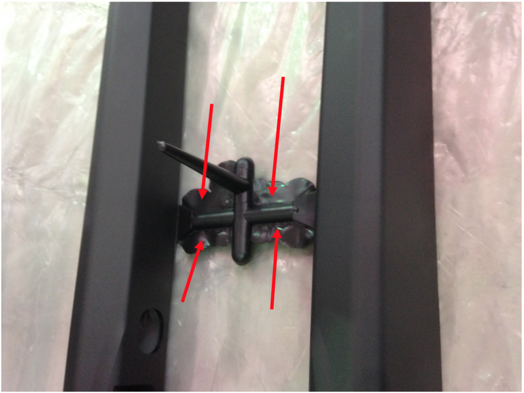
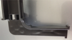
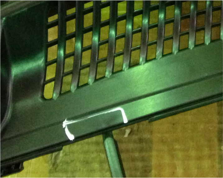
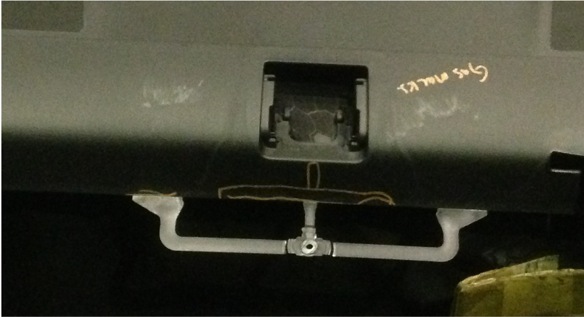
16. Ejector Pin Marks
- Background
Ejector pin marks are really a sticking problem and should be considered as such. SEE No.15 Part Sticking. See illustration in Pic.-13 and Pic.-14
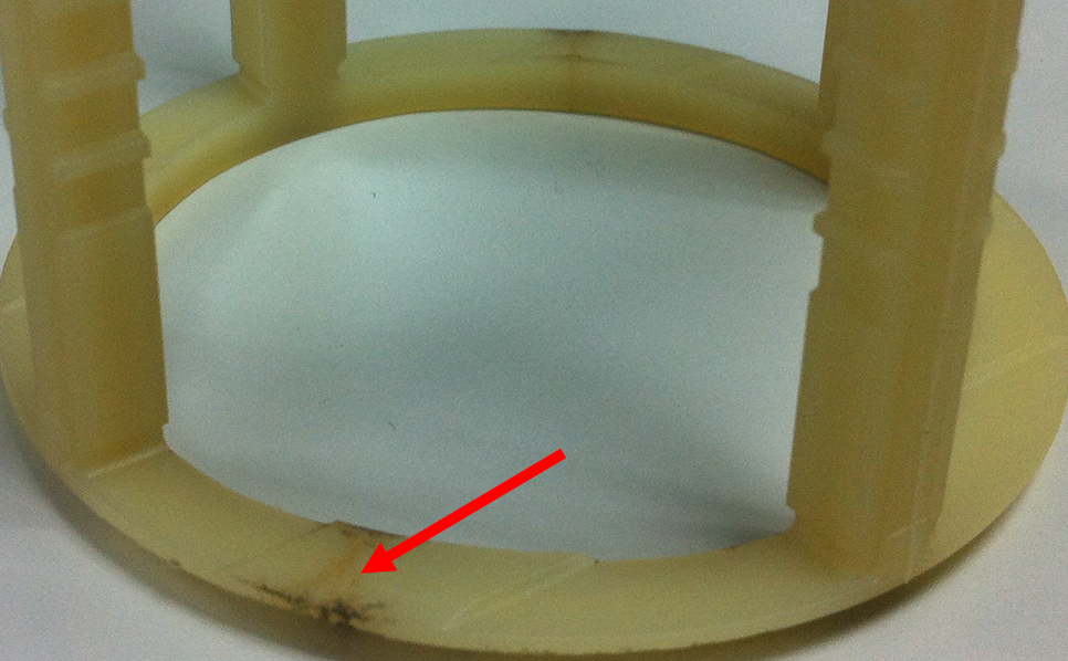
17. Black Spots
- Background
Black specks may develop from several sources including Dead spots or hang up in the barrel, old material that has not been cleaned or purged during a material change, and material contamination prior to material entering the barrel. See illustration in Pic.-15. - Possible Countermeasure
- Proper purging
- Clean the screw and barrel completely
- Check for dead spots of material and correct
- Check for excessive screw or barrel wear that may cause stagnant material or excessive shear.
- Check for causes of contamination in the material handling system.
- Check incoming material from the supplier to ensure it is not the source.
18. Cracking
- Background
This could be led by- Mechanical problem
It happens during the ejection or part sticking, which could be caused by overpacking or subsequent handling. - Material
It could be caused by some degradation of the physical properties; it is a chemical problem caused by contamination of the material by an additive or foreign substance. This situation will generally be accompanied by a reduction in viscosity of the material.
- Mechanical problem
- Possible Countermeasure
- Check viscosity of the material
- Reduce the amount of holding
- Detect improper post mold handling techniques if appropriate
- If viscosity is low, change to virgin material
- Check regrind viscosity and determine if it has been contaminated
- Check the draft on the part to eliminate sticking
- Check chemical resistance of plastic with any chemical or soap the plastic contacts
19. Delamination
- Background
It generally involves contamination with dissimilar material that is not compatible. This will also generally result in lowering viscosity and reduced physical properties. - Possible Countermeasure
- Change material and retry
- Analyze material
- Compare viscosity of material to a virgin batch using the injection fill integral to see if material is degraded or contaminated
20. Brittleness
- Background
Generally, a brittleness caused by degradation will show a marked change in the viscosity of the plastic. Other possible causes are contamination of a material that will also cause a loss of viscosity and too much regrind in a virgin/regrind blend. - Possible Countermeasure
- Check the temperature of the plastic
- Check residence time
- Check viscosity
- Check cause of viscosity variation
- Change to another material batch
- Check dryer
- Check regrind area and virgin for contamination
- Check melt temperatures and mold temperatures for proper conditions to ensure crystallinity.
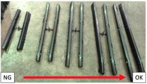
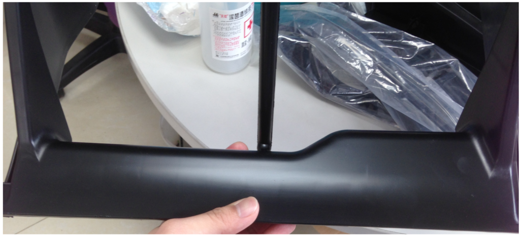
21. Warp
- Background
- Warp is a complex phenomenon, generally caused by some kind of stress induced in the part during filling, holding, or cooling.
- The stress could come from crystallinity induced caused by non-uniform cooling, Compressive stress gradients caused by non-uniform holding pressures, orientation stresses caused by flow and subsequent relaxation of the stresses during cooling.
- Generally,
- Part made of crystallinity material has more possibility to warp then part made of amorphous material.
- Parts filled with long thin fibers, such as glass has more possibility to warp then part not/less percentage filled.
- Analyzing the problem
- Categorize material as crystalline or amorphous, fiber-filled or unfilled.
- Run the part with both crystalline and amorphous material:
Easy flow ABS and PP could a good combination. If the ABS part does not warp and the polypropylene part does, crystallinity issues are probably the cause. - In semicrystalline material
Comparing the first shot out of a cold or uniformly-temperatured mold to one run later as the mold warms up. If the first part out of the mold is not warped, then the issue of non-uniform cooling is probably the predominant situation. - More about Crystalline Materials
Analyzing warp in parts made of long fiber-filled materials involves comparing parts molded with the fiber to that of the unfilled polymer to determine the degree of change. Flow during fill orients fibers in the direction of flow, but they do not de-orient as many molecules do during cooling.- Possible Countermeasure-a
Re-design the cooling to minimize hot spots and cold spots in the mold.
Change the material to an amorphous polymer.
Re-design the part to a more rigid structure using complex shapes or ribs (ribs are least desirable).
- Possible Countermeasure-a
- Amorphous Unfilled Materials
Generally, amorphous warp is caused by a combination of orientation stresses and a holding stress gradient. A holding stress gradient can be reduced by reducing viscosity, generally by increasing fill rates and/or temperatures. Orientation stress can be reduced by raising the plastic temperature, slowing the fill, and/or reducing the cooling rate.
Another important factor is whether the gate is sealed. The holding stress gradient can be reduced by intentionally not sealing the gate, which will reduce the compressive stress gradient by allowing back flow, thus making the part flat. This is especially true in center-gated parts, both semi-crystalline and amorphous.- Possible Countermeasure-b
Increase fill speed
Decrease fill speed
Increase melt temperature
Increase mold temperature
Reduce injection time to allow gate to back flow or discharge
- Possible Countermeasure-b
- Run the part with both crystalline and amorphous material:
- Categorize material as crystalline or amorphous, fiber-filled or unfilled.
22. Dimensional variations-Part is too small overall
- Background
Plastic pressure throughout the cavity is too low. - Possible Countermeasure
- Increase holding pressure to obtain required in-mold pressures
23. Dimensional variations-Part is too large overall
- Background
The pressure distribution throughout the cavity is too high. - Possible Countermeasure
- Reduce holding pressure to obtain cavity pressure required
24. Dimensional variations-Part is too small close to gate
- Background
The effective plastic pressure near the gate is too low while the pressure in the rest of the part is okay. This generally is caused by the gate being unsealed. - Possible Countermeasure
- Increase injection forward/holding time or determine the root cause, such as possible increase of plastic temperature
25. Dimensional variations-Part is too large close to gate
- Background
The pressure distribution in the mold at the gate end is too large, the rest of the pressure is okay. - Possible Countermeasure
- Reduce holding pressure; possibly change the pack rate if possible
- Check melt temperatures; may be too high
- Check material viscosity
- Allow discharge by reducing injection forward/hold time
26. Dimensional variations-Part is too small at the end of filling
- Background
Pressure distribution is okay at the gate but is reduced from normal at the end of fill. This generally indicates a change in plastic viscosity. - Possible Countermeasure
- Check fill time
- Check melt temperature and adjust as appropriate
- Check viscosity. If viscosity is too high, increase fill speed until the viscosity is correct.
27. Dimensional variations-Part is too large at the end of filling
- Background
This means that the pressure distribution in the cavity is okay at the gate and too high at the end-of-fill. This indicates a lowering of viscosity. - Possible Countermeasure
- Check fill time
- Check melt temperature and adjust as appropriate
- Check viscosity. If viscosity is too high, increase fill speed until the viscosity is correct.
28. Dimensional variations-Dimensional Inconsistency
- Background
Inconsistent dimensions mean inconsistent pressure gradients throughout the part.- Observed on some shots
It indicates the gate is sealing or not sealing which pressure distribution in the cavity is varying on a shot-to-shot basis. - Observed with trends over time
It indicates temperature variations or material lot variations, or pressure changes due to check ring leaks, etc.
- Observed on some shots
- Possible Countermeasure
- Run a series of short shots to check the check ring consistency
- Monitor hydraulic pressure consistency
- Do a gate seal analysis and possibly increase injection forward time
- Monitor viscosity fluctuations
- Monitor in-mold pressure to determine variability.
29. Process Problems-Hot Runner Blockage
- Background
- Hot runner blockage, especially during start-ups, can be caused by a heat sink in the system causing heat to be transferred from the hot manifold into the mold.
- Check mold temperatures in the areas around the manifold to determine hot spots.
- Possible Countermeasure
- Insulate the hot runner manifold from the mold
- Check thermocouple location and heater integrity
- Bench check hot manifolds for temperature uniformity for installation in the mold
- Check for metal or other foreign materials in the mold since this is a contaminated material
- Check for unmelt granules in melts.
30. Process Problems-Hot Runner Shorts (random in cavities)
- Background
Generally, it is caused by non-uniform flow lengths or temperature from the nozzle into the drop areas. - Possible Countermeasure
- Proper temperature control
- Increase fill times
- Proper runner design
31. Process Problems-Nozzle Drool
- Background
Nozzle drool is caused by improper temperature control at the nozzle and improper use of decompression. Sometimes drooling is a symptom of large reductions in viscosity of material that have been degraded. - Possible Countermeasure
- Better temperature control at the nozzle
- Proper use of decompression that is large enough to eliminate drool and not enough to induce trapped air
- Proper diameter nozzle
- Check for degraded material viscosity
32. Process Problems-Nozzle Freeze-Off
- Background
Nozzle freeze-off is generally caused by too much heat being drawn from the nozzle into the sprue bushing. This means that there is insufficient heat at the nozzle caused by an inappropriate heater band, the improper location of the heater band, or most often, a thermocouple location improperly chosen. - Possible Countermeasure
- Insulate the nozzle from the sprue bushing using paper or another insulating material
- Relocate the thermocouple
- Increase the heater band size
- Reduce nozzle tip orifice diameter
33. Process Problems-Nozzle Stringing
- Background
- Stringing at the nozzle is a drawing of the material out into a fine strand between the sprue and the nozzle. Stringing is caused by material viscosity conditions that do not promote detachment. Changing the nozzle or tip temperature or geometry can correct stringing.
- Sometimes the strand can be broken by using decompression. Decompression after screw run can break the string and sometimes decompression before screw run used alone or with decompression after screw run can be effective.
- Possible Countermeasure
- Adjust nozzle or tip temperature
- Adjust melt temperature
- Change nozzle size or tip size
- Use decompression after screw run
- Use decompression before screw run
- Use both forms of screw decompression
34. Process Problems-Occasional Part Hang-up
- Background
On a running machine, occasional part sticking is generally due to fluctuations in pressures inside the mold. Part sticking randomly at different cavities or continually in same cavity is the most input for analyzing this problem. Short shot cavity balance analysis can be an important part of analyzing this problem. - Possible Countermeasure
- Determine mold balance
- Monitor in-cavity pressure to determine the range of variation
- Check mold for correct polishing
35. Process Problems-Sprue Sticking
- Background
It is led by a mismatch between the nozzle and the sprue or damage to the sprue causing an undercut. - Possible Countermeasure
- Correct mismatch between nozzle and sprue bushings
- Reface the sprue bushing nozzle interface
- Repolish the sprue bushing in the draw direction
- Change the sprue bushing