In most cases, the molding process operates at the environment where technician also works at, it is normal environment we are living at which is full of air. Within the molding cycle, the mold cavity area is full of air when the mold closes/before the step injection (melt plastic fills the cavity area) starts. To keep the melt plastic stays inside the cavity area (the plastic goes out of cavity area calls flash), the mold shall be closed completely. Furthermore, the force to close/clamp the mold shall be big enough to compensate the injection pressure, it means that the mold is clamped very tight by injection molding machine (IMM) while step injection.
Since the mold is clamped so tight and space inside cavity area is occupied by the air, the melt plastic must fight with the air for the space during injection. It could lead to the cavity area cannot be filled by melt plastic well, and it could lead to short shot on part.
It is not a good part either if it has flash or short shot, we can work with the parting surface to prevent both. From an opened mold and we see the front view of fixed and moving side, see illustration in Pic.-1. It normally consisted of cavity area(green), parting line(red), and parting surface(yellow), see Pic.-2.


Since the fluidity of melt plastic is much lower than air, we can create path for air to leave mold and still keep the melt plastic inside cavity area by reducing the area of parting/matching surface. The path for air is venting and it can be added at the area close to parting line area. It is a part of mold design, and it looks like “dent” made by CNC machining during mold manufacturing. And venting shall be distributed regularly and appropriately adjusted according to raw material type, gate location, part design…etc. See illustration of venting(blue) in mold in Pic.-3.

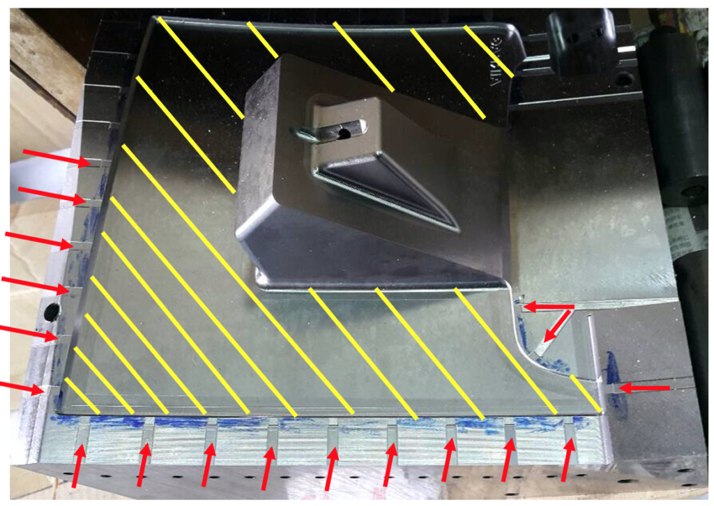
The air starts leaving mold from cavity area, parting line, venting, until atmosphere. Therefore, venting can have full functionality only if it reaches the outside of parting/matching surface. Since the end of venting has no critical concern since it does not relate to part, the area (black) can be removed by machining directly, see illustration in Pic.-4 and actual mold example in Pic.-5.

Note: Reducing the matching area could increase the producibility since bigger matching surface requires more clamping force and mold/IMM accuracy.

Note: Yellow: part area, Blue: parting line area, Red arrowhead: Venting.
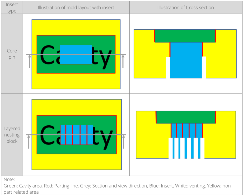
If there is air trap at the center area of part, it can not be solved by adding venting mentioned above. Since air can leave cavity through parting line, we can add parting line at the air trap area in mold to improve venting. Additional parting line can be generated by adding insert (blue), see illustration in Pic.-6.

The insert for venting has two popular design, see illustration in Table-1:
